13

May . 2022

How to create a smaller and lighter PFC with fast-switching TRENCHSTOPTM 5 IGBT and a SiC diode

Share to

Compact dimensions and reduced system costs are design goals, which developers in power electronic designs always pursue. Now, because of the ever-growing amount of energy consumed by home appliances, engineers working on such applications have an additional goal: maintaining a high power factor (PF). Especially air conditioners, with power ratings of 1.8 kW or more, are amongst the power-hungriest devices. Here, a power factor correction (PFC) is mandatory and for PFC, designers regard IGBTs (Insulated Gate Bipolar Transistors) as being the most appropriate switching devices in terms of cost-performance ratio.


In PFC systems, a lower switching frequency increases the size of the boost inductor. As a result, developers cannot place it on the main circuit board. In this case, the price of the inductor is inevitably high, and the form factor of the system is limited, rendering the other design goals nearly impossible. Additionally, the likelihood of a short circuit (SC) event occurring during installation or maintenance tends to favor the selection of an IGBT with a SC withstand capability for protection.


To ensure short-circuit capability, the Vce(sat) and switching performance of the device are reduced, and the device will be less performant. Consequently, the demand for integrating the PFC inductor on the main board by increasing the switching frequency continues to rise. Doing so will minimize the system‘s form factor and weight, reduces the cost of the inductor, and enables the use of high-performance IGBTs.
High switching frequencies enable smaller inductances


The most common topology for active PFC circuits is a boost converter. For the power factor correction in major home appliances, the continuous conduction mode (CCM) is used, as there are lower conduction losses due to lower RMS currents and fewer harmonics, which makes the design of the EMI filter easier.


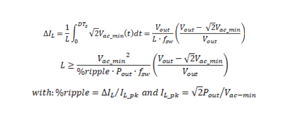
The inductor ripple in a CCM PFC boost converter reaches its maximum when the instantaneous value of the AC input is equal to Vout/2. However, for a high-power CCM PFC, the minimum AC input voltage, Vac_min, is approximately at least 180 V and its peak value is always higher than Vout/2. The required inductance L for continuous conduction mode power factor correction is calculated by using the following equations.

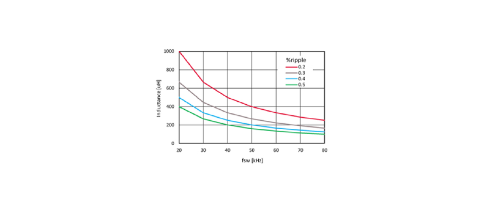
Figure 1: Inductance vs. switching frequency for Pout=2.5 kW, and Vac_min = 180 V

The higher the inductance, the lower is the current ripple. But, a larger inductance leads to an increase in cost. The PFC can maintain CCM operation as long as ∆??/2 is less than ??. Therefore, it is necessary to choose the optimal inductance in terms of cost and performance. Figure 1 shows the required inductance for a CCM PFC as a function of the switching frequency. It reveals that the inductance becomes much smaller at higher switching frequencies. Once the frequency exceeds 60 kHz, it gets small enough to be placed on the main board.

Infineon’s TRENCHSTOP™ 5 WR5/WR6 IGBT family offers the best-in-class performance in terms of both conduction and switching characteristics. In particular, when the device is used with a SiC diode as a complementary switch, switching losses are significantly reduced, enabling operation at high switching frequencies beyond 60 kHz. In addition, this IGBT family features an optimized monolithically integrated diode suitable for boost converter PFC applications where a high current rated co-pack diode is uneconomical. The IGBT’s anti-parallel diode does not conduct during normal load operation in the CCM boost converter. But under transient or light-load conditions, a reverse current can flow through the device that is very small in magnitude and lasts only for a very short period of time. As a result, the current rating requirement for the anti-parallel diodes is not very high, so the diode integrated in the WR5/WR6 IGBT is sufficient for this atypical operation. This makes the TRENCHSTOP™ 5 WR5/WR6 IGBT a cost-effective option.


To verify the validity of this solution, we used the IKW40N65WR5 device out of the TRENCHSTOP™ 5 WR5 IGBT family and compared its electrical characteristics with those of a CoolMOS™ P7 MOSFET (Metal-Oxide-Semiconductor Field-Effect Transistor) of equivalent rating.

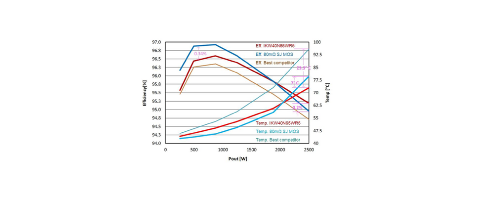
Figure 2: Efficiency and thermal performance test results at fsw = 60 Hz for an IKW40N65WR5 IGBT, a CoolMOS™ P7 MOSFET and the competitor’s best performing 40 A IGBT

IGBTs show the best performance


Figure 2 shows the efficiency and thermal performance of the IKW40N65WR5 IGBT, the 80 mΩ CoolMOS™ P7 MOSFET, and a competitor’s best performing IGBT at a switching frequency of 60 kHz.


The results show that the IKW40N65WR5 IGBT outperforms the competitor’s IGBTs in both efficiency and thermal performance over the entire load range.


Between IKW40N65WR5 IGBT and the competitor’s device, the maximum temperature gap is more than 23°C and the efficiency gap is about 0.3% at the maximum load. In addition, IKW40N65WR5 IGBT shows better thermal and efficiency performance than the equivalent CoolMOS™ P7 MOSFET at about 2 kW and above. In contrast, the equivalent CoolMOS™ P7 MOSFET performs slightly better in the low- to mid-load range.

The results shown in Figure 2 suggest that the CoolMOS™ P7 MOSFET would be ideal for light load conditions. For major appliances, such as air conditioners, where full-load conditions are very important, the TRENCHSTOP™ 5 WR5 IGBT is clearly the best choice considering cost and performance. By using a TRENCHSTOPTM 5 WR5 IGBT and a SiC diode, it is possible to increase the switching frequency of the PFC stage to 60 kHz. This reduces the required inductance significantly, saving weight and space, and making it feasible to mount the PFC inductor directly onto the main board.


Furthermore, the TRENCHSTOPTM 5 WR5 IGBT shows a far better efficiency and thermal performance in high-frequency operation than the best-performing competitor’s device. Compared to the equivalent CoolMOSTM P7 MOSFET, the IKW40N65WR5 IGBT has a superior efficiency and temperature characteristics at around 2 kW and above.

Semiconductor Components Inquiry Form
If you have any questions related to our products (qutation, technical support, product documents, sample request, cooperation, etc), please kindly fill the inquiry form. Your inquries will be replied as soon as possible.
Privacy Policy

STEP

01
!

Marked Please fill in the required field, thank you.

Need
Industry

Product

Notes

Next, fill in contact information

STEP

02
!

Marked Please fill in the required field, thank you.

Company Name
Department
Contact Person
Title
Phone number
eMail
Address
Delivery Address
Trading company or not
Verification Code
Subscribe to Newsletter
!

Marked * Please fill in the required field, thank you.

Company Name
Department
Name
Title
Contact Number
Select preferred newsletter language
Email
Verification Code